Why The Safety Mechanism Shall Live Outside The Core In Some Cases?
Dipl.-Ing. Tolga Kizilirmak
Why The Safety Mechanism Shall Live Outside The Core In Some Cases?
An Automotive Hardware/Firmware Architecture Case Study
By Tolga Kizilirmak · A Retrospective On My 2018 Master’s Thesis
What should a controller do when the measurement it trusts is wrong?
This question captures the central challenge of my master’s thesis at TU Graz, conducted with Infineon in 2018. I investigated how a cost-sensitive automotive alternator-control integrated circuit could retain a low-cost ARM Cortex-M0 while addressing an Automotive Safety Integrity Level B (ASIL B) target for overvoltage protection. The most useful outcome was an architectural direction: use firmware for complex regulation, and place independent protection in dedicated hardware outside the processor core, within the same chip.
My task was to decide which functions belonged in each domain and what evidence would support that allocation. The Cortex-M0 itself was not being certified by this work.
The Decision Was Bigger Than The Processor
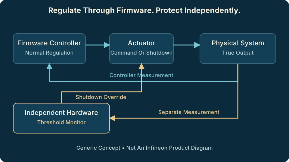
An alternator controller adjusts excitation current to regulate a vehicle’s electrical supply. Firmware makes increasingly complex regulation functions easier to implement and adapt as well as providing cost and area reductions. Protection has a different responsibility: intervene when normal control can no longer be trusted.
Moving that protection into firmware would therefore involve more than writing another function, especially when you are using a non-safety-compliant core such as Cortex-M0. The processor, memories, measurements, and supporting platform would also need an appropriate safety argument. My investigation considered fault-tolerant processor architectures, hardware and software safety assessment, safety patterns, and methods for structuring that argument.
For this application, the additional flexibility of firmware-based protection did not justify the estimated area and engineering effort of the redundant platform considered. The comparison favored simpler hardware mechanisms supervising normal firmware operation. Those estimates were specific to the alternator-control case; a more general-purpose product with changing safety requirements could justify a different balance.
A simplified separation of responsibilities: firmware regulates; an independent hardware path can override the actuator. Original teaching diagram, not a product schematic.
Fault Injection: Make The Measurement Lie
Consider a measurement that reports a voltage lower than the actual output. The controller may respond logically to that incorrect input and continue increasing excitation. A second check using the same corrupted measurement would inherit the same problem. Where does the independent information come from?
In the thesis, I combined firmware with C models of the physical circuitry in closed-loop simulation. Normal-operation and fault-injection scenarios exercised the overvoltage mechanism, including faults in the voltage-measurement path. The simulated independent hardware protection took over when the firmware’s measurement channel no longer represented the physical condition correctly.
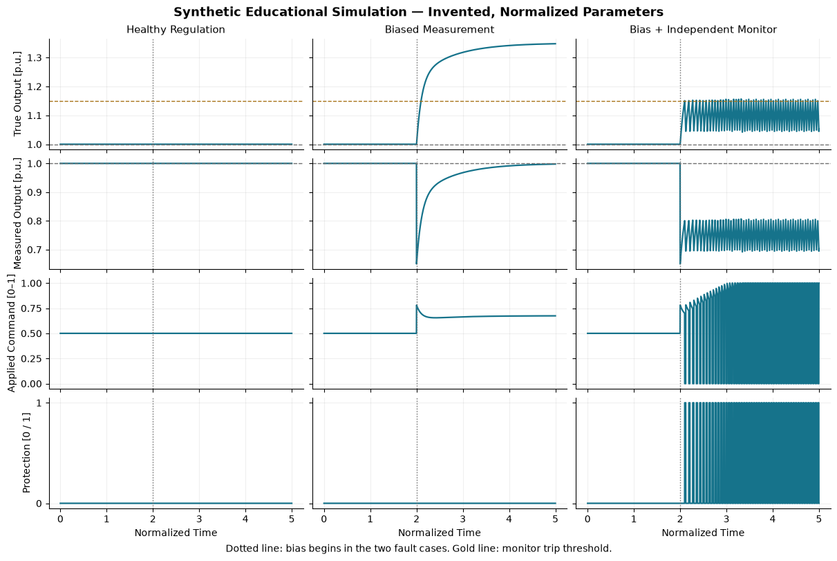
The small experiment below illustrates that principle with an entirely new model. It compares healthy regulation, a biased controller measurement without protection, and the same bias with an independent threshold monitor. All values are invented and normalized; these are synthetic educational results, not the thesis traces or an electrical model of the Infineon device.
The monitor observes the model’s uncorrupted output. Above its upper threshold, it overrides the command with zero; below a lower threshold, it releases the override. This hysteresis avoids switching at a single boundary. The resulting cycling also makes an important limit visible: detecting a threshold crossing does not mean the output never exceeds that threshold.
Before examining the protected case, compare the true and measured outputs in the middle column. Notice what the controller believes it has achieved while the physical output continues to rise.
Explore The Teaching Model
# Synthetic educational simulation; no company code, data, or parameters.# Requires Python 3, NumPy, and Matplotlib. Run deliberately in Jupyter.# Tested with Python 3.14, NumPy 2.5.4, and Matplotlib 3.11.2.import numpy as npimport matplotlib.pyplot as pltDT, DURATION, FAULT_TIME =0.002, 5.0, 2.0TARGET, TRIP, RELEASE =1.0, 1.15, 1.05TIME = np.arange(0.0, DURATION + DT /2, DT)def simulate(bias=0.0, protection=False): voltage, integral, active =1.0, 0.5, False rows = []for t in TIME: measured = voltage + (bias if t >= FAULT_TIME else0.0)if protection:if voltage >= TRIP: active =Trueelif voltage <= RELEASE: active =False error = TARGET - measured requested =float(np.clip(0.8* error + integral, 0.0, 1.0)) command =0.0if active else requested rows.append((voltage, measured, command, float(active)))# Freeze integration during override; clamp it to bound wind-up.ifnot active: integral =float(np.clip(integral +1.5* error * DT, 0.0, 1.0))# Invented first-order plant: equilibrium output = 2 * command. voltage += DT * (2.0* command - voltage) /0.25return np.asarray(rows)runs = [simulate(), simulate(-0.35), simulate(-0.35, True)]healthy, unprotected, protected = runs# Checks establish this example's behavior, not real hardware safety.assert np.allclose(healthy[:, 0], TARGET)assert unprotected[-1, 0] >1.30assert np.any(protected[:, 3] ==1)assert np.all(protected[protected[:, 3] ==1, 2] ==0)assert np.all(protected[TIME < FAULT_TIME, 3] ==0)assert protected[:, 0].max() < unprotected[:, 0].max()titles = ['Healthy Regulation', 'Biased Measurement', 'Bias + Independent Monitor']with plt.rc_context({'font.size': 10, 'axes.titlesize': 11,'axes.spines.top': False, 'axes.spines.right': False}): fig, axes = plt.subplots(4, 3, figsize=(12, 8), sharex=True, sharey='row', layout='constrained') labels = ['True Output [p.u.]', 'Measured Output [p.u.]','Applied Command [0–1]', 'Protection [0 / 1]']for column, (title, data) inenumerate(zip(titles, runs)): axes[0, column].set_title(title)for row inrange(4): ax = axes[row, column] ax.plot(TIME, data[:, row], color='#16738b', linewidth=1.6) ax.axvline(FAULT_TIME, color='#707070', linestyle=':', linewidth=1) ax.grid(alpha=0.2)if column ==0: ax.set_ylabel(labels[row])for row in [0, 1]: axes[row, column].axhline(TARGET, color='#707070', linestyle='--', linewidth=1) axes[0, column].axhline(TRIP, color='#a77318', linestyle='--', linewidth=1) axes[3, column].set_yticks([0, 1]) axes[3, column].set_xlabel('Normalized Time') fig.suptitle('Synthetic Educational Simulation — Invented, Normalized Parameters', fontsize=13, fontweight='bold') fig.supxlabel('Dotted line: bias begins in the two fault cases. Gold line: monitor trip threshold.', fontsize=10)plt.show()
Figure 1: Synthetic educational simulation with arbitrary parameters. Columns compare healthy regulation, a biased measurement, and the same bias with an independent monitor.
The healthy case stays at its target. With the biased measurement, the unprotected system settles above it. The independent monitor instead interrupts the command and drives the output downward. Read the true and measured signals together: the controller’s view and the physical state have diverged.
This model assumes perfect independent observation and an ideal shutdown actuator. It omits electrical dynamics, faults in the protection path, and shared causes of failure. Both paths also run in one Python process. Real independence requires analysis of measurements, references, supplies, clocks, and actuation; the teaching model establishes none of those properties for hardware.
Try A Small Change
Open a notebook in Jupyter and run the code cell shared above. In the runs list, change both fault-case biases from -0.35 to -0.45, then run it again. The unprotected true output should settle higher, while the monitor still interrupts the protected command. Keep the two biases equal for a fair comparison. The assertions check the example’s intended behavior.
An Architecture Decision Needs A Traceable Argument
The simulation was one part of a wider investigation. I also established a requirements structure in JAMA for the overvoltage-protection reference implementation, connecting safety goals, detailed requirements, hardware/software allocation, and verification activities. Change-impact analysis and a reference fault tree helped connect the design decision to the evidence it would require.
Here is an invented example of that connection:
Requirement
Allocation
Verification Question
Detect excessive output independently of controller feedback
Separate monitor path
Does a fault in controller feedback leave detection available?
Override the normal command after detection
Protection-to-actuator interface
Is the override applied within the specified response time?
Release protection only under defined conditions
Recovery behavior
Are release and repeated threshold crossings handled as specified?
The wording is deliberately incomplete as a product specification: thresholds, timing, operating conditions, and failure assumptions must be defined. Its purpose is to show how a diagram becomes a set of questions/requirements that can be verified. If a threshold changes, those links help identify the monitor requirement, interfaces, and tests that need attention.
For me, the lasting value of this work is that connection between breadth and decision. Investigating processor architectures, safety patterns, analysis methods, and traceability helped me identify a practical direction for one product. The thesis provided a proof of concept and a foundation for further safety engineering. A completed product-wide safety case and ASIL certification remained outside its scope. (But in the end, we managed to develop an ASIL D compatible version of the product after some years, using a completely different approach) For this specific product application, the recommendation kept the flexibility of firmware where it was useful and gave the protection mechanism a smaller, more manageable implementation to analyze.
Research Context
Tolga Kizilirmak, A Case Study for an Alternator Control ASIC with Automotive Safety Integrity Level ASIL B, master’s thesis, Graz University of Technology, 2018. Architecture discussion: §3.5; implementation and simulation: §4.3.2; comparison and traceability: §§4.2.1 and 4.4.1; conclusions: Chapter 5. The diagram, Python model, plot, and requirement examples here are new explanatory material. No company source code, original product diagrams, or JAMA screenshots are reproduced.